PT FTS Indonesia
Tailored specifically for wear resistance and long life in lubricating fluid service. They are designed to handle a wide range of fluids at temperatures to 200°F, at pressures up to 150 psi, and at shaft speeds to 1750 RPM. Viscous liquids require reduced shaft speeds.
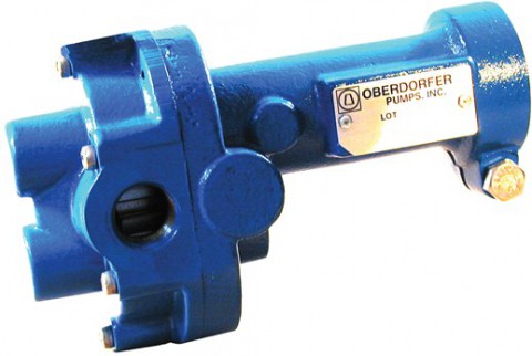
Gear Pump C992
FEATURES
- Ductile Iron Construction
- Stainless Steel Shafts
- Ferrous Gears (Optional 416 Stainless Gears)
- Nitrile Mechanical Seal (Optional fluoroelastomer or EPDM Mechanical Seal)
- Process Lubricated Carbon Bearings
- O-Ring Cover Seal for Maximum Leak Protection
- Durable Paint Finish
- Easy Field Assembly to a Variety of Motor Frames
- Compact Dimensions
DRIVE
These pumps are bidirectional. The standard pump motor unit is set up for normal rotation (counter clockwise when viewing the pump from the shaft end). Reversing the motor rotation will reverse the “in” and “out” ports and also requires changing the relief valve location. C992R is equipped with an integrated relief valve set up for internal bypassing. The relief valve must always be located on the inlet side of the pump. This relief valve is not intended to be a metering or flow control device. Its purpose is to function as a discharge pressure relief to guard against intermittent downstream system restrictions. Overheating can occur within 5 to 10 minutes if the discharge line is completely shut off. The pressure relief setting is not set at the factory. To increase pressure, turn the relief valve adjusting screw in a clockwise direction. DRIVE ARRANGEMENT These close-coupled pumps mount directly to a full range of NEMA and IEC C-face motors by means of a suitable adapter bracket. The clamp style cover also allows adapter-less close coupling to modified 48 Frame 1/3rd and 1/2 HP motors. The pump drive shaft is connected to the motor shaft by a flexible coupling. Complete pump and motor units are available.
LIQUIDS & TEMPERATURES
Standard Lubricating Fluid Service: Shafting is 303 stainless steel, gearing is ferrous (optional 416SS gears). Rugged ductile iron housings. High grade carbon-graphite bushing style bearings are used. The Standard Mechanical Shaft seal is a stainless cased Nitrile elastomer bellows and o-ring with carbon and ceramic wear faces. An optional fluoroelastomer mechanical seal with carbon and ceramic wear faces is also available. Recommended liquid temperature range is 32°F to 200°F. Non Lubricating or High Temp Service: see C992M3F6 As with all external gear rotary pumps which operate based upon close running clearances, the presence of solid particles and abrasives can lead to premature wear and damage. Use suction screens or start-up strainers when
SUCTION LIFT
Whenever possible, place the pump at an elevation below the liquid source. However since these positive displacement external gear pumps will generate 20″ HG lift, this is not a requirement. As a general rule, place the pump as close to the liquid source as possible. For a first start-up, the pump should be primed to avoid dry running. Minimum size of the suction pipe is the size of the pump inlet port. For longer suction lines (over 3 feet), the pipe size should be at least one size or two sizes larger than the pump inlet port.
Order Enquiry Form
Contact form description text


