PT FTS Indonesia
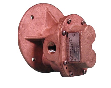
Pump housings and gears are made of top quality bronze, shafts are stainless steel 303. Bearings are made of high performance carbon-graphite material selected for wear resistance and long service life. Gear pumps are positive displacement pumps. Each shaft revolution displaces a definite amount of liquid relatively unaffected by the back pressure in the discharge line. Shaft speed and flow are directly proportional.
Gear Pumps N994
FEATURES
- Bronze Construction with Stainless Steel Shafts
- Helical gears for quiet operation
- Easy Field Assembly to Motors
- Self-Lubricating Carbon Bearings
- O-ring seal for maximum leak protection
- For clutch driven version, see N994-38
- Lip or Mechanical Seal
- For Danfoss hydrolic motor driven pump units
DRIVE
Close coupled pumps are mounted directly to the electric motor by means of a suitable adapter bracket. The pump drive shaft is connected to the motor shaft by a flexible coupling.
LIQUIDS & TEMPERATURES
These pumps are suitable for all liquids that are compatible with bronze. Most common liquids are water, oil, and mild chemicals in the pH-range of 4 to 11. Viscous liquids require reduced shaft speeds of 1150 RPM or lower. Consult factory. Liquids containing solids, abrasives, powders or paint pigments are definitely not recommended for gear pumps. If abrasives are unavoidable, use a very low shaft speed. See price book for the recommended liquid temperature range of lip and mechanical seals. Freezing of water-filled pumps can cause damage and must be avoided. Oils at low temperatures are very viscous requiring a lower speed or extra power.
SUCTION LIFT
As a general rule, the suction lift should be kept at an absolute minimum by placing the pump as close to the liquid source as possible. A gear pump in new condition can lift 20 feet of water in the suction line. A foot valve (preferably with built-in strainer) is recommended at the beginning of the suction line. For a first start-up, the pump should be primed to avoid dry running. Minimum size of the suction pipe is the size of the pump inlet port. For longer suction lines (over 3 feet), or for viscous liquids, the pipe size should be at least one size or two sizes larger than the pump inlet port.
ROTATION AND RELIEF VALVE
The relief valve is not intended to be a metering or flow control device. Its main purpose is to function as a discharge pressure relief when the spring tension is exceeded by the discharge pressure. Overheating can occur within 5-10 minutes if the discharge line is completely shut off for extended periods. Unless otherwise specified, the pump motor unit is supplied by the factory for shaft rotation clockwise from shaft end. Reversing the motor rotation will reverse the “in” and “out” ports and also requires changing the relief valve location. The relief valve is always on the discharge side in this pump series. The factory pressure setting is 50 PSIG. To increase pressure, turn the relief valve adjusting screw in a clockwise direction. To reverse single phase motors, find instructions on the inside of the junction box cover or on the name plate of the motor. Three phase motors are not wired for any particular rotation. They can be reversed by interchanging any two (2) wires of the three (3) wire leads.
Order Enquiry Form
Contact form description text


